



Introduction: 2010, the Mechmate Forum
Around 2010. A CNC router community wanted to add CAM capabilities to the community edition of QCAD 2.0.5.
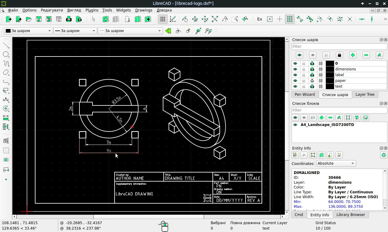
QCAD CE was tied to the Qt3 library at the time. It had to be ported to Qt4 first. That porting job took the project somewhere else: it started as CADuntu and soon became LibreCAD [1].
The irony sits right there: LibreCAD began for CAM, and today it does no CAM. What it does is produce CAM’s input. The 0.00 mm hairline you see on screen becomes a real cut path on a laser. The bridge is DXF.
The motif of this review is the hairline. Because LibreCAD’s value is not in how thin the line looks, but in where that line goes.
LibreCAD is a GPLv2, open-source 2D CAD application for Windows, macOS and Linux [1][2]. It uses AutoCAD DXF as its working format and offers layers, dimensioning, blocks, hatching and printing tools [3][4][5].
LibreCAD at a Glance
| Developer | Volunteer community; roots in the 2010 QCAD CE fork [1][7] |
|---|---|
| Current Version | 2.2.1.6 — 17 October 2026 (maintenance release); 2.2.2 alpha is a separate line [6][7] |
| Licence | GPLv2 (GPL-2.0-only) [1][7] |
| Scope | 2D drafting only; isometric views are a 2.5D representation, not 3D modeling [3] |
| Platforms | Windows, macOS, Linux; community builds for Haiku [1][7] |
| DXF Support | Read/write: R12, R14, 2000, 2004, 2007; DWG import at a basic level [5] |
| Drawing Tools | Layers, pens, line types, blocks, hatching, text, command line, snapping [3][4] |
| Dimensioning | Aligned, horizontal, vertical, linear, radial, diametric, angular and leader [4] |
| Package Sizes | Windows x64 84.6 MB; macOS ARM64 98.8 MB; Linux x86-64 AppImage 82.8 MB [6] |
| Missing | 3D solid modeling, parametric constraints, assemblies, built-in CAM [3][8] |
First Turn: It Began for CAM and Became a Drafting Tool
LibreCAD’s origin explains its present limit.
The project started to add CAM capabilities to QCAD CE for Mechmate CNC router users [1]. But porting from Qt3 to Qt4 turned out to be a bigger job than adding CAM. Over the years, under the names CADuntu and then LibreCAD, it became a 2D drafting application [1][7].
Today LibreCAD has no CAM module. It does not produce toolpaths, does not compensate for cutter radius and does not manage post-processors. What it does is produce the input for those tasks: a clean, layered, scaled DXF.
That is not a failure; it is a clear division of labour. But it matters to the user. Someone who says “I will do laser cutting with LibreCAD” is really saying “I will prepare a file for laser cutting with LibreCAD”.
Second Layer: DXF Is the Native Language
LibreCAD’s native working format is DXF; it imports and saves using that format [7]. That does not make it a “little AutoCAD”, but it lets it talk to the AutoCAD ecosystem.
The supported versions are limited and explicit: R12, R14, 2000, 2004 and 2007 [5]. For newer DXF versions, the official answer is to convert the file to a compatible version. The project’s own FAQ says it plainly: LibreCAD does not support all features of the Autodesk DXF format [5].
DWG is even more limited. LibreCAD can import DWG at a basic level; if the import fails, the user is advised to convert to DXF [5]. DWG is not the native language. It is a guest language.
For laser and CNC shops this is usually not a problem. Most cutting software reads DXF R12 or 2000. But in an architectural project, a file from a consultant using a newer DXF version can be a problem. Before buying, ask your supply chain which DXF version it uses.
Third Layer: Layers, Pens and the Hairline
The most mature side of LibreCAD is its 2D drafting discipline.
Every entity has a “pen”: colour, line width and line type. Pen properties can be assigned to a single entity, a selected group or a layer [3]. The default line width is 0.00 mm, the hairline. The upper limit is 2.11 mm, and the values in between include ISO line widths [3].
Layers are the main way to organise a drawing. Every entity can belong to only one layer; a layer carries pen properties in bulk, and individual entities can override them [3]. Construction layers do not appear in print and hold infinite helper lines [3].
This structure is directly useful for laser and CNC preparation. Cut, engrave and helper geometry go on separate layers; the cutting software maps those layers by colour or name. But note: LibreCAD does not interpret a layer as a “cut order” or a “tool”. That mapping happens in CAM.
The hairline matters here too: a line that reads 0.00 mm on screen is not zero-width in the real world. The laser or blade has its own width. Kerf compensation is not LibreCAD’s job; it is CAM’s. LibreCAD only supplies correct geometry.
Fourth Layer: Dimensioning and Printing
LibreCAD takes the language of technical dimensioning seriously.
It offers aligned, horizontal, vertical, linear, radial, diametric and angular dimensions, plus leaders [4]. Dimension components — text height, arrow size, extension-line gaps — are set in drawing preferences. The manual says that when the print scale changes, “General Scale” must be set to the inverse of the print scale [4].
This is an important trap for users used to scaling dimensions with the drawing. A drawing printed at 1:4 needs General Scale 4; otherwise the dimension text comes out at the wrong size on paper [4].
The manual also lists dimensioning rules: every dimension should have one interpretation, dimension and extension lines should not cross, each entity should be dimensioned once, and long dimensions should sit outside shorter ones [4]. These are not LibreCAD-specific; they are the conventions of technical drawing. But the fact that the program writes them into its manual shows its target audience: engineering and architectural drafting.
Fifth Layer: Laser and CNC Preparation
LibreCAD’s place in the laser and CNC ecosystem is that of a preparation desk.
The flow is usually this: draw 2D geometry, separate layers, add dimensions and notes, export DXF. The cutting software imports the DXF, maps layers, applies kerf compensation and produces the toolpath. LibreCAD is the first link in that chain [1][5].
The project’s own sponsor page shows the connection: PCBWay accepts DXF files for sheet-metal, laser-cutting and bending quotes [1]. The ecosystem is built around “produce DXF, hand it to CAM”.
Practical points to watch:
1. Closed contours. Laser cutting needs a closed path. An open line becomes an engrave or a bad path. Use trim and extend to close the contour [3].
2. Scale and units. DXF carries units, but cutting software may interpret them differently. Model at real size (1:1) and do not confuse model scale with print scale [4].
3. Layer mapping. Cut, engrave and helper geometry should live on separate layers. Otherwise the cutter will also cut dimension lines.
4. DXF version. Does your cutting software read R12 or 2000? LibreCAD can write from R12 to 2007; choose the right version [5].
5. Kerf. Cutter-width compensation is not in LibreCAD. It is applied in CAM. The geometry that leaves LibreCAD is nominal geometry.
Third Turn: The Limit of 2D
“LibreCAD does not do 3D” is technically true but incomplete. What it does not do is 3D solid modeling. What it does do is represent a 3D object in 2D.
The manual describes isometric views as “sometimes referred to as 2.5D” [3]. So there is a three-axis drawing plane, but no volume, mass, assembly or parametric relation.
That limit defines the product. LibreCAD is not the “little brother” of a 3D modeler; it is the tool of a separate discipline: technical drawing. If you do not need a 3D model to produce a manufacturing drawing for a part, LibreCAD is enough. If you need the assembly, interference checks or volume, you need another tool.
Parametric constraints are absent too. Change a dimension and the geometry does not update automatically; you edit the line and the dimension separately. On simple drawings that is a speed cost; but in 2D drafting, parametric modeling is often unnecessary complexity.
Fourth Turn: Versions, Community and the Future
The current stable line is 2.2.1.x. Version 2.2.1.6 was published on 17 October 2026 [6]. The release notes call it a maintenance release: bounded hyperbolas, right-to-left MText, CJK fonts, small-screen layouts and a long list of fixes [6].
The 2.2.2 alpha line runs separately and is not recommended for regular use [7]. LibreCAD 3 is a fully rewritten experimental branch; it targets Lua scripting and a new interface, but development stalled after 2023 and the project refocused on LibreCAD 2 [7].
On the community side, the honest picture is mixed. An independent CAD survey in 2023 reported that LibreCAD struggled to attract regular contributors, lost two prolific contributors, and that the v3 branch was far from releasable [9]. That does not mean the software is dying; it means the roadmap is uncertain.
Maintenance releases still arrive. For a 2D drafting program, that is what most users need: not radical novelty, but stability.
Learning Curve: An Afternoon or a Week?
Two correct statements describe LibreCAD’s learning curve.
The first is that basic drawing is fast. An independent review in 2012 found the interface “easy to use” and said there was “not much of a learning curve” [8]. For someone with AutoCAD experience, the menus and handle logic are familiar [7].
The second is that a standards-compliant technical drawing takes longer. Layer discipline, dimension scale, line widths, print settings and DXF versions are not learned in an afternoon [3][4]. The program is easy; technical drafting is hard.
A simple analogy: learning LibreCAD is like learning to hold a ruler and a set square. Learning drafting conventions is a separate education.
Who It Fits, and Who It Does Not
A good fit: workshops preparing 2D DXF for laser, plasma and waterjet; offices doing architectural plans, electrical layouts and site drawings; schools teaching technical drawing and engineering graphics; small teams without an AutoCAD licence budget; machine shops drawing simple parts for production [1][8].
A poor fit: teams doing 3D solid modeling, assemblies and interference checks; users expecting parametric feature history; anyone wanting built-in CAM strategies and post-processors; teams needing cloud collaboration and version management; anyone who must work directly with newer DXF versions (2010 and later) [3][5].
A middle group: users leaving AutoCAD but not ready for 3D. For them, LibreCAD is a free continuation of a familiar 2D habit.
A Short Comparison With Alternatives
| Tool | Approach | Difference From LibreCAD |
|---|---|---|
| QCAD | 2D, commercial plus community edition | LibreCAD’s ancestor; a more mature 2D tool set and commercial support, but the full edition is paid. |
| FreeCAD | Parametric 3D plus 2D workbenches | 3D and drafting under one roof; heavier and with a steeper learning curve. |
| Autodesk Fusion 360 | Cloud-connected 3D CAD | 3D model, CAM and simulation; too heavy for 2D drafting and subscription-based. |
| AutoCAD LT | Commercial 2D standard | Wider DXF/DWG compatibility, supply-chain familiarity and support; licence cost. |
| Inkscape | Vector graphics | Strong for visual and artistic vectors; no dimensioning, layer discipline or DXF drafting flow. |
The decision sentence: LibreCAD is the tool for people who want to draw in 2D and hand off DXF. It is not the tool for people who want to model in 3D and manage a production line.
Closing: Where Does the Hairline Go?
LibreCAD’s default line is 0.00 mm. On screen it is almost invisible. But if that line is on the right layer, at the right scale, and forms a closed contour, it becomes a laser’s cut path.
The program’s value is there: unglamorous accuracy. It does not do 3D, CAM or cloud. It has done one thing — producing clean 2D geometry — for years.
One-sentence answer: LibreCAD is a solid 2D preparation tool for laser, CNC and technical drawing; for 3D design and production management, it is the wrong layer.
A step for today: draw a bracket, separate cut and engrave layers, export DXF R12 and send it to a cutting service. The program’s whole job shows up in those three steps.
Two questions: which DXF version does your production chain read? And who does the CAM in that chain?
Sources
- LibreCAD, official website — history, GPLv2, platforms, community and the PCBWay DXF link; accessed 7 November 2026. librecad.org
- LibreCAD User Manual, introduction — GPLv2 and manual scope; accessed 7 November 2026. docs.librecad.org
- LibreCAD User Manual, “Fundamentals” — coordinates, layers, pens, line widths, isometric 2.5D; accessed 7 November 2026. docs.librecad.org
- LibreCAD User Manual, “Annotating a Drawing” — dimension types, scale and printing rules; accessed 7 November 2026. docs.librecad.org
- LibreCAD Wiki, “FAQ” — DXF R12/R14/2000/2004/2007 support and basic DWG import; accessed 7 November 2026. dokuwiki.librecad.org
- GitHub, “LibreCAD v2.2.1.6” — 17 October 2026 release, package sizes and release notes. github.com/LibreCAD/LibreCAD
- Wikipedia, “LibreCAD” — accessed 7 November 2026; secondary source for version, licence, platforms, history and LibreCAD 3 status. en.wikipedia.org/wiki/LibreCAD
- Jack Wallen, “DIY: LibreCAD offers basic CAD tools for free”, TechRepublic — 27 January 2012. techrepublic.com (archive)
- Alexandre Prokoudine, “A survey of free CAD systems”, LWN.net — 6 February 2023. lwn.net (archive)