



Introduction: The 1.0 Tag After Twenty-Two Years
18 November 2024. The FreeCAD wiki page for “Release notes 1.0” opened with a flat sentence: “FreeCAD 1.0 was released on 18 November 2024.” After twenty-two years of 0.x version numbers, the project had finally attached a 1.0 tag to its parametric modeler.
That tag is not a certificate of perfection. The project’s own announcement says it plainly: “This version 1.0 is not a finished product.” For 1.0, the community had chosen two remaining milestones: the topological naming problem and a built-in assembly module. Both were “solved” — and neither was “finished”.
That distinction sits at the center of any honest review. You buy CAD software by reading a feature list, but you live with it by opening last year’s model and finding that it still rebuilds. FreeCAD 1.0 is the project’s first serious answer to the second question.
FreeCAD at a Glance
| Developer | FreeCAD community / FreeCAD Project Association (FPA) |
|---|---|
| First Release | 29 October 2002 |
| Version 1.0 | 18 November 2024 |
| 1.0.2 Patch | 6 August 2025 |
| Licence | LGPL-2.1-or-later |
| Kernel | OpenCASCADE Technology (OCCT) |
| Interface | Qt and Coin3D |
| Language | C++ and Python 3.11 |
| Platforms | Windows 8/10/11 64-bit; macOS 10.12+ (Intel and ARM); Linux x86_64/aarch64 AppImage |
| File Formats | FCStd, STEP, IGES, STL, OBJ, DAE, DXF, SVG, IFC |
| Price | Zero; no subscription or seat licence |
This review covers the 1.0 family, meaning the line from 1.0.0 to 1.0.2. Version 1.1 arrived on 24 March 2026 as a separate release; its changes belong in a different article [1][2][5].
What 1.0 Actually Promises: A Model That Survives the Next Edit
For years, FreeCAD’s most talked-about defect was topological naming. When you applied a pad, cut, union, chamfer or fillet to a part, the internal names of the shape could change. A later sketch that referenced one of those names would move, fail, or quietly attach itself to the wrong face. The FreeCAD wiki explains that the issue comes from the way the OCCT kernel updates shapes, and that it is not unique to FreeCAD [1][7].
Version 1.0 brought Realthunder’s naming algorithm into the main branch. The official release notes say the work took more than a year and that the initial implementation landed through PR #13705. The same page adds a warning: “The TNP problem is not completely solved and further improvements will follow in the next version” [1].
Here is the first turn. “TopoNaming is fixed” does not mean “every model is now stable forever”. The algorithm has three jobs: identify broken references when possible, offer a likely repair, and resolve a reference automatically when it is confident enough. The wiki describes this as “identify, propose, automatically resolve”, and notes that the code deliberately avoids aggressive automatic repairs because a wrong repair can hide the real problem [7].
So 1.0 does not make topological naming disappear. It makes the failure visible and repairable. That is a more honest engineering promise. Every parametric CAD application can lose references when geometry changes; the difference is how early and how clearly the tool tells you.
There is a human story here as well. The release notes dedicate 1.0 to Bradley McLean (bgbsww), one of the main architects of the naming effort. He died a few weeks before the release. He wrote a large amount of code and tests, became the project’s TNP specialist, and helped other developers adapt to the new algorithm. A version number rarely shows that layer of work [1].
Assembly Moves into the Core
The second major promise of 1.0 is the built-in Assembly workbench. For years, FreeCAD users assembled parts with add-ons such as Assembly4 and A2plus. Version 1.0 moved that job into the core and based it on the open-source Ondsel Solver. The basic workflow is straightforward: open an assembly document, insert parts as links, ground one part, connect the others with joints, set offsets and limits, then test the motion. Exploded views and a bill of materials are also available [1][3].
The same honesty applies here. Libre Arts’ launch review notes that the 1.0 assembly workbench was primarily bottom-up: you model the parts separately, then bring them together. The official notes describe the basic joint functionality as present while development continues [1][3]. For large, deeply nested assemblies, flexible sub-assemblies, and heavy motion studies, commercial CAD still has more headroom.
Even so, this is a real threshold. Assembly is where single-part modeling ends and mechanical design begins. Building a bracket is one skill; attaching that bracket to a motor mount, a shaft bearing and a housing is another. Version 1.0 gives that discipline its first official core answer.
Sketcher and PartDesign: Where the Daily Work Changed
The steepest part of FreeCAD’s learning curve has always been Sketcher and PartDesign. Version 1.0 did not just repaint them. It changed the rhythm of ordinary modeling.
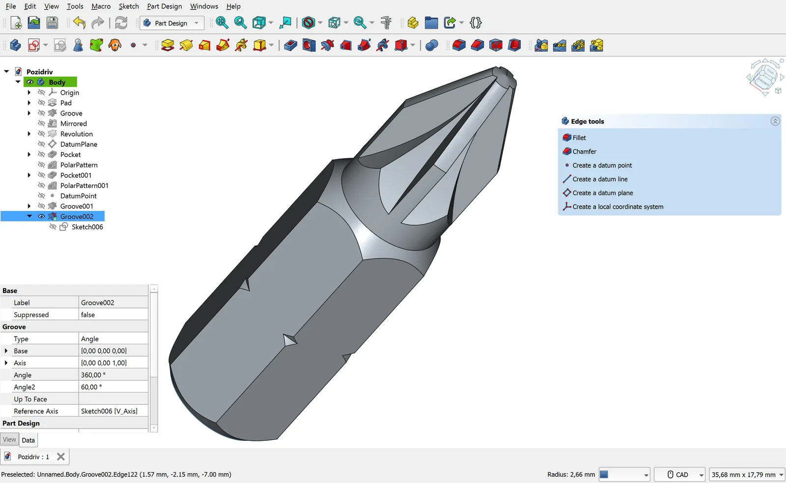
The most visible Sketcher addition is the contextual Dimension tool. Older versions expected you to pick a separate tool for distance, angle, radius or diameter. The new tool chooses the appropriate dimension type from the selection, and the “M” key cycles through the available modes. On-view parameters let you type values while drawing. Offset, Scale, Move, Rotate, a basic Chamfer, continuous Trim, and copy/paste with constraints all arrived in this release. Copied sketch geometry is also placed on the clipboard as Python commands, so it can move between sketches or even between FreeCAD sessions [1][3].
These are small-sounding changes that save hours in daily use. The Dimension tool reduces the “which constraint goes where” hesitation that greets new users. The automatic horizontal/vertical constraint applies whichever orientation is closer, and picking the midpoint of a line now brings in a symmetric constraint. The release also adds three-point rectangles, arc slots and B-spline tangency [1].
PartDesign received equally practical changes. Pad can now end on multiple faces with the “up to shape” mode. Revolution and Groove gained “to first”, “to last”, “up to face” and “two dimensions” options. Linear and polar patterns gained an Offset mode, while the old behavior was renamed “Overall Length”. Helix received a long list of fixes. An experimental Allow Compound option permits multiple solids inside a single body, a workflow that feels familiar to people arriving from other CAD packages [1][3].
The second turn: none of this makes FreeCAD as smooth as Fusion 360. The limiting factor is not the number of tools; it is how those tools follow each other. In 1.0, attaching a sketch directly to a face can still produce extra work when that face changes. The FreeCAD wiki continues to recommend datum planes and explicit placement for stable models. Version 1.0 does not make that advice obsolete; it just warns you earlier when a reference breaks [7].
Still, the cumulative effect is that PartDesign now clears the “I can model a serious part” bar. A bracket, flange, enclosure or printable replacement part has a complete tool chain. Complex surfaces, large assemblies and tightly toleranced production drawings still demand patience and discipline.
CAM: A Reliable 2.5-Axis Workhorse, Not a Five-Axis Shop
In FreeCAD 1.0, the Path workbench became the CAM workbench. The rename came with real maturation. A new OpenGL-based simulator is faster and more precise. V-carve gained step-down, a finishing pass and head-movement optimization; the release notes say these changes can improve carved surface quality while raising carving speed by up to 50%. Rest machining now reads the G-code of earlier operations, so it can follow non-Area operations such as Adaptive [1][3].
Knowing the limits is part of using CAM well. The FreeCAD wiki states that most CAM tools are not true 3D tools but 2.5D tools: they take a fixed 2D shape and cut it to a given depth. Two operations produce true 3D paths: 3D Pocket and 3D Surface, and the latter is still experimental. Waterline is experimental as well. Lathe tools remain under development. Most operations assume a standard endmill even when the tool controller describes something else; Engrave and 3D Surface are the exceptions [4].
The third turn: this does not make FreeCAD CAM a toy. It makes it a focused tool. For sawing, drilling, 2.5D pockets, profiles, facing, engraving and V-carve work, it is more than enough. For continuous five-axis machining, turning, complex 3D surface finishing or automatic clamp-collision checking, it is the wrong address. The wiki also warns that operations are not aware of clamping devices, so you must simulate the job before sending G-code to a machine [4].
That boundary defines the audience. For a hobby shop, a small production run, a prototype or a wood-and-metal 2.5D workflow, the CAM workbench is a credible zero-cost option. For an industrial production line, it needs a CAM specialist and probably a commercial post-processor.
Python Console and Macros: The Quiet Superpower
What separates FreeCAD from many open-source CAD tools is not that it has a Python API. It is that Python sits inside the application rather than beside it. Version 1.0 moved to Python 3.11. That brings a compatibility issue for older macros: the methods used by Python features to save and restore custom data, __getstate__ and __setstate__, were renamed to dumps and loads. If you maintain an old macro, those two methods are the first thing to check [1].
The new App::VarSet object offers a cleaner alternative to spreadsheet aliases and older Dynamic Data workflows. Design variables live next to the model and remain accessible to scripts running in headless mode. Expressions can now use Vector API functions [1][3].
What does that mean in practice? You can drive a part’s dimensions from a VarSet, then reuse the same values in FEM boundary conditions and CAM stock dimensions. You can write a macro that opens hundreds of STEP files, measures them, produces a report or builds TechDraw pages. You can customize a CAM post-processor in Python. You can copy sketch geometry as Python commands and move it to another model [1][4].
But Python power is also maintenance. Writing a macro means learning FreeCAD’s internal API, and that API can change between releases. The Python 3.11 transition is the concrete example. If nobody on the team owns “FreeCAD automation”, macros can quietly rot. For a small team trying to remove repetitive work, though, this is far more accessible than the paid API tiers of commercial CAD.
Licence: Free, but Not Unconditional
FreeCAD is distributed under the LGPL-2.1-or-later licence. In practice, you can use it for commercial work, sell it, and modify it. If you distribute a modified version of the library, you must provide the source and preserve the recipient’s ability to relink against a modified library. If you use it internally and do not distribute it, most of those obligations do not come into play [6].
That distinction matters when “free” is used as a synonym for “unrestricted”. FreeCAD itself carries no licence fee, but add-ons may use different licences. If you embed a CAM post-processor or a custom workbench in a commercial product, check that add-on’s terms separately. The same applies to anyone shipping FreeCAD as part of a server product.
The licence has another consequence: the roadmap does not belong to one company. Commercial ventures come and go. The assembly solver in 1.0 is Ondsel Solver, and Ondsel was shutting down in 2024. The solver remained open source and stayed inside FreeCAD. That is the concrete benefit of the licence: the company can leave, but the code remains [3].
Platforms: Strong on the Desktop, Absent in the Browser
FreeCAD 1.0 shipped official packages for Windows, macOS and Linux. The 1.0.2 download page lists 64-bit Windows 8/10/11, macOS 10.12 Sierra and later, and Linux AppImages for x86_64 and aarch64. The package names include py311, confirming Python 3.11 builds [5].
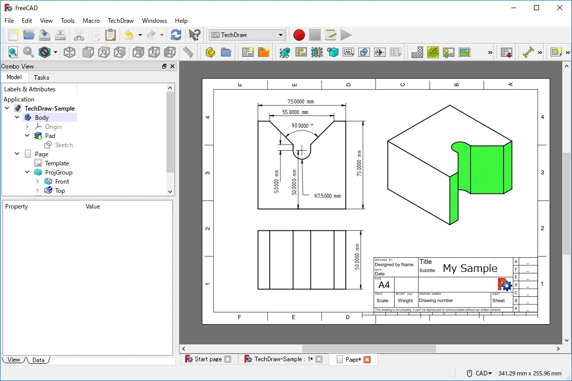
Windows gets an installer and a portable `.7z`. macOS gets separate Intel and Apple Silicon `.dmg` images. Linux gets AppImage builds, plus distribution repositories, Snap and a daily PPA. FreeCAD can also run headless through freecadcmd, which makes it usable in a server pipeline; 1.0 added tab completion to the headless Python console. The application is built on OCCT, Coin3D and Qt, a stack that Phoronix also highlights in its launch coverage [1][5][10].
What is missing: an official web version or a mobile app. If you want the browser-based experience of Onshape, FreeCAD is the wrong address. macOS support also has a floor; do not expect an official package below 10.12. On Linux, your distribution’s package may lag behind, so an AppImage, Flatpak or Snap is usually the safer route to the current release.
Learning Curve: Different and Crowded, Not Impossible
FreeCAD’s learning curve softened in 1.0, but it remains steep. Three reasons stand out.
First, the workbench model. You are not using one program; you are using a set of connected workbenches: Sketcher, PartDesign, Part, Draft, CAM, TechDraw, FEM, BIM. A single job may require three or four of them. That gives experienced users flexibility, and gives new users the question “where do I start?”
Second, there is more than one way to do the same thing. You can build a solid in PartDesign, in Part, or in Draft. Which one is “correct” depends on how you intend to update the model later. Without a good teacher or a good template, that freedom can be confusing.
Third, there is terminology and documentation. The FreeCAD wiki is extensive, but not every page has the same freshness. Some tools added in 1.0 still carry an “experimental” label. Those labels deserve respect; simulate an experimental CAM operation before putting it into a production line.
Against that, 1.0 cleaned up the interface: the measure tool was unified, the task panel became dockable, dark and light themes arrived, and a new start page and safe mode were added. These changes do not flatten the curve, but they reduce the cost of the first day [1][3].
Strengths and Weaknesses
| Strengths | Weaknesses |
|---|---|
| Zero licence fee; no subscription for commercial use | Steep learning curve; the workbench model can overwhelm newcomers |
| Parametric solid modeling with open formats such as STEP, IGES and IFC | Less fluid than commercial CAD on large assemblies and complex surfaces |
| TopoNaming repair makes the feature tree more resilient | The repair is not complete; datum discipline still matters |
| Full Python automation, headless operation and custom post-processors | API changes can break macros; ongoing maintenance is required |
| Windows, macOS and Linux, including ARM builds | No official web or mobile version; no real-time team collaboration |
| Broad module set: CAM, FEM, BIM, TechDraw and more | CAM is mostly 2.5-axis; turning and five-axis work are limited |
| LGPL licence; no vendor lock-in | Limited corporate SLA, certified support and training ecosystem |
Who Should Choose It — and Who Should Not
FreeCAD 1.0 may be right for you if:
- Your budget is close to zero and you do not want another subscription.
- You use Linux, or you prefer open-source tools on Windows or macOS.
- You work in 3D printing, woodworking, a small shop, prototyping or 2.5D CNC.
- You want to automate repetitive work with Python.
- You are a student, teacher or hobbyist with time to learn.
- You care that your files will still open a decade from now; FCStd and STEP are open, documented formats.
FreeCAD 1.0 is probably not right for you if:
- You work daily in very large assemblies with thousands of parts.
- You need certified production drawings, advanced GD&T and auditable revision control.
- You do Class-A surfacing, advanced NURBS or complex industrial design.
- You need continuous five-axis machining, turning or advanced CAM strategies.
- You want real-time cloud collaboration, browser access or a mobile app.
- You require per-seat certified training and 24/7 enterprise support.
A Short Comparison with the Alternatives
| Tool | Position | Difference from FreeCAD |
|---|---|---|
| Autodesk Fusion 360 | Cloud-connected CAD/CAM/CAE | Free personal tier, subscription for commercial work. CAM and user experience are more mature, but the cloud and licence dependencies are real [8]. |
| Onshape | Browser-based SaaS CAD | Strong real-time collaboration and browser access. The free plan is generally limited to public documents; commercial use requires a subscription. |
| SOLIDWORKS | Windows desktop, enterprise standard | Strong assembly, drawing and supply-chain integration. High cost, Windows dependency and maintenance subscription [9]. |
| Rhino 3D | NURBS surface modeling | Excellent for free-form surfaces, jewelry, architecture and industrial design. Less suited to parametric solid modeling and assembly; perpetual licence model. |
| Blender | Mesh, sculpting, animation, rendering | Excellent for visual production and animation; not a parametric solid CAD tool for manufacturing output. GPL licensed [8]. |
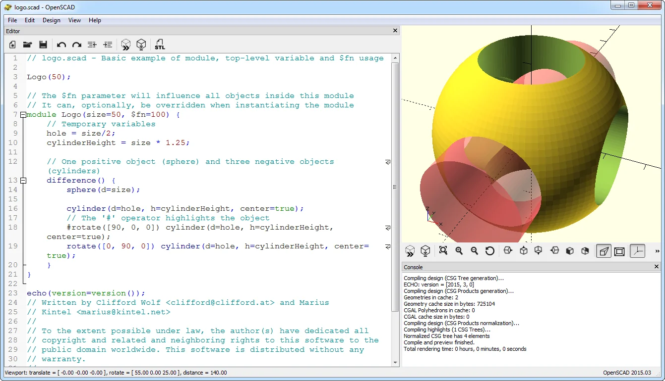
| OpenSCAD | Code-based CSG | Very strong for repeatable, scripted design; limited on complex surfaces and large assemblies. |
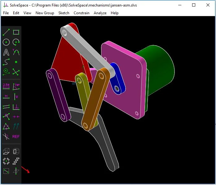
| SolveSpace | Lightweight parametric 2D/3D | Small, fast and easy to learn; behind FreeCAD in features and ecosystem. |
This table does not crown a winner. Each tool is a different link in a different production chain. FreeCAD’s place is the intersection of parametric solid modeling, open formats, Python automation and zero licence cost.
Closing: 1.0 Is a Tag, Not a Warranty
Open FreeCAD 1.0 for the first time and you do not see a celebration. You see a workbench. The new logo, the dark theme and the tidier preferences show that a twenty-year-old project has cleaned itself up. The real difference is that changing a sketch no longer makes the model fall apart quite as easily. For a user, that matters more than a logo.
Do not oversell 1.0, though. TopoNaming repair is incomplete; CAM is still mostly 2.5D; large assemblies demand patience; the Python API demands maintenance. FreeCAD is not a program that does everything. It is a program that lets you build your own workflow. Judge it as a toolkit, not as a shrink-wrapped product.
The maturity of a CAD program is measured not by how many features it adds, but by how many old models still rebuild when you open them. On that measure, 1.0 offers the first serious answer.
So what should you do? Before choosing the tool that will draw your model, choose the format in which you will open that model ten years from now. And when you test 1.0, aim for a working feature tree in the first hour, not a perfect result.
Sources and Verification
- FreeCAD Documentation, “Release notes 1.0” — wiki.freecad.org (archive: web.archive.org)
- FreeCAD News, “FreeCAD Version 1.0 Released” (19 November 2024) — blog.freecad.org
- Libre Arts, “FreeCAD 1.0: new features and the larger picture” (19 November 2024) — librearts.org
- FreeCAD Documentation, “CAM Workbench” — wiki.freecad.org/CAM
- FreeCAD Documentation, “Download” — wiki.freecad.org/Download
- FreeCAD GitHub repository, LICENSE (GNU LGPL 2.1) — github.com/FreeCAD/FreeCAD
- FreeCAD Documentation, “Topological naming problem” — wiki.freecad.org/TNP
- DigiLiner, “3D Modeling Software in 2026: A Comparison of 24 Tools” — digiliner.org
- DigiLiner, “SOLIDWORKS Review” — digiliner.org
- Phoronix, “FreeCAD 1.0 Released With UI/UX Improvements, New Materials System” (19 November 2024) — phoronix.com