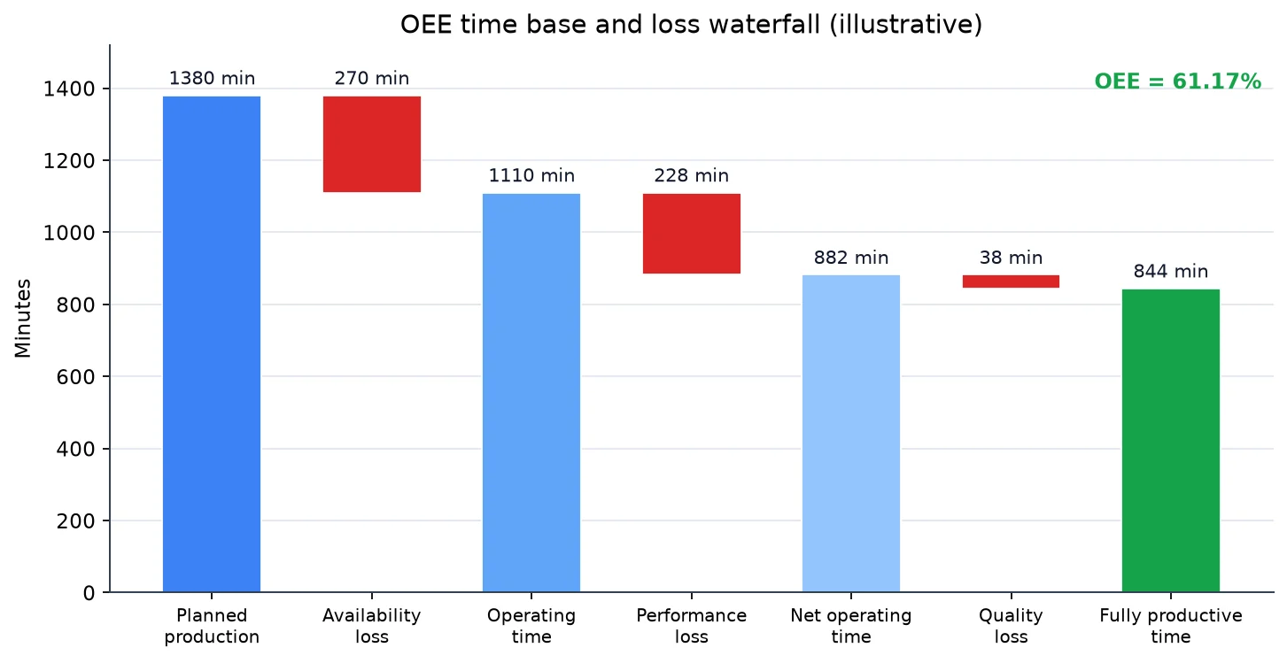





You have a CNC machine without an Ethernet port, incapable of speaking FOCAS or MTConnect. You want to see this machine on your plant-wide OEE dashboard. The immediate instinct is to attach external sensors. While this is entirely feasible, adding sensors does not mean discovering everything the internal controller knows from the outside. External sensors measure electrical and mechanical behavior. From these signals, cutting, standby, and alarm states can be inferred; product quality, ideal cycle time, or the root cause of an alarm cannot be directly read.
This engineering guide outlines the minimal retrofit hardware package for a CNC machine lacking a digital interface, identifies which signals genuinely drive operational decisions, and defines the practical limits that must be acknowledged when feeding data into an OEE framework. The foundational principle is straightforward: define the decision-making requirement first, then select the instrumentation. Inverting this order inevitably yields industrial data pollution.
First Decision: Is Retrofit Necessary?
Not every older machine tool justifies a sensor deployment. The decision matrix below summarizes the operational evaluation required before purchasing hardware. The engineering objective is not maximizing data volume, but providing data for missing shopfloor decisions:
| Current State | First Action | Is Retrofit Justified? |
|---|---|---|
| Controller features Ethernet, FOCAS, OPC UA, or MTConnect. | Utilize existing interfaces first; audit license status and tag quality. | Generally no; external sensors represent redundant capital expense. |
| No digital interface; stack light and auxiliary PLC contacts accessible. | Begin with stack light optocouplers + split-core CT; defer vibration monitoring. | Yes; a low-cost, minimal package is technically sufficient. |
| No digital interface; machine is mechanically sound and heavily utilized. | Deploy three-signal suite + edge IPC; gather 1–2 weeks of baseline data. | Yes; effectively eliminates operational blind spots in OEE. |
| No digital interface; low machine utilization, single shift, small batch work. | Evaluate manual dispatch tracking or stack light monitoring alone. | Doubtful; instrumentation and maintenance costs often exceed payback. |
| Electrical cabinet neglected, mechanical defects present, or safety compromised. | Execute electrical maintenance and mechanical overhaul first. | No; sensors highlight dysfunction, they never resolve baseline machine faults. |
What Can Be Measured, What Cannot?
The principal hazard in external sensor retrofit is expecting more than the physics of the sensors can deliver. The table below details what operational indicators are realistically captured after retrofit:[3]
| Metric | Retrofit Capability | Engineering Rationale |
|---|---|---|
| Cutting / Idle / Alarm | Yes, conditional | CT current, vibration, and stack light states combine to segment operating modes; accuracy depends on calibration. |
| Availability | Partially | Differentiates run vs stop; planned vs unplanned stoppage requires production calendars and operator downtime reasons. |
| Performance | Partially | Measures active cutting time; calculating OEE Performance requires ideal cycle time baselines and verified part counts. |
| Quality | No | External sensors cannot verify part geometry or scrap rates without automated post-process inspection or manual entry. |
| Energy Consumption | Yes, conditional | Active power requires simultaneous voltage references and true-RMS measurement; CT alone yields current, not real power. |
| Tool Wear Progression | Trend-based only | Tracks relative RMS shifts; remaining tool life requires structured baseline runs across identical speeds, feeds, and alloys. |
| Root Cause of Failure | No | Sensors flag an anomaly; pinpointing whether it originates from spindle bearing spalling, unbalance, or tool deflection demands specialized diagnostics. |
The Minimal Hardware Package
For an isolated machine tool lacking communication ports, the standard minimal package consists of three signal streams: main spindle current, spindle bearing vibration, and stack light status. This configuration reliably segments “cutting / standby / alarm” conditions. It does not replace the CNC controller. Additional sensors should only be introduced if they alter an explicit shopfloor decision.
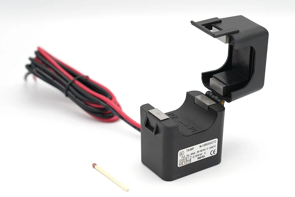
1. Split-Core Current Transformer: Capturing Cutting Load
A split-core current transformer (CT) clamps directly over an insulated phase conductor without circuit disassembly. Its chief benefit is rapid installation without modifying factory wiring harnesses. However, mechanical simplicity does not guarantee measurement fidelity. Critical engineering requirements include:[2]
- Measurement point: The input power leads to the spindle inverter (VFD) represent overall cutting load. Measuring inverter motor output leads introduces high carrier frequency PWM noise; measuring downstream requires dedicated true-RMS transducers engineered for VFD switching.
- CT ratio sizing: Normal cutting load should operate between 50% and 80% of the transformer primary rating. Over-sizing sacrifices resolution during light finishing passes; under-sizing causes core magnetic saturation during heavy roughing.
- Secondary circuits: A current transformer secondary must never be routed directly into raw analog inputs without an appropriate burden resistor or 4–20 mA / 0–10 V signal conditioner. Never operate a current transformer with an open secondary circuit; an open secondary generates dangerous inductive voltages. Ensure shorting blocks are installed prior to cabinet work.
- Measured variables: Current measurement alone provides amperes; active power (kW) necessitates synchronized voltage references and power factor calculation. True-RMS current suffices for operational state tracking; calculating energy metrics requires a dedicated power meter.
- Sampling rate: State classification algorithms perform robustly at 1–10 Hz sampling. High-speed current signature analysis or micro-tool breakage detection requires 1–10 kHz data rates, requiring high-bandwidth DAQ hardware rather than standard Modbus RTU bus modules.
2. Accelerometer: Assessing Mechanical Dynamics
Vibration amplitudes characterize the mechanical condition under which cutting proceeds. Instrumentation falls into two primary categories:
- IEPE Piezoelectric Accelerometers: Characterized by wide frequency response (typically 0.5 Hz to 15 kHz), these sensors are well suited for early bearing fault detection and chatter identification. They require constant-current excitation and high-speed DAQ modules. Rigid stud mounting directly into machine castings is necessary for high-frequency fidelity; magnetic mounts are acceptable for initial trend assessment, not permanent monitoring.
- Smart MEMS / 4–20 mA Sensors: These units execute onboard filtering and edge computation, transmitting overall velocity RMS (mm/s) or acceleration peak values directly to PLCs or edge gateways. They simplify integration, although they omit high-frequency spectra needed for deep bearing defect isolation.
Vibration severity should be evaluated against the ISO 20816 standard series, which formally supersedes the older ISO 10816 standards.[1] Accelerometers must be positioned directly on rigid spindle housing castings adjacent to the front bearings; thin sheet metal covers, protective bellows, or motor cowlings are mechanically invalid mounting surfaces.
3. Stack Light / PLC Contacts: State Context
Current and vibration establish whether physical rotation and cutting occur; the stack light provides the machine context. Green typically denotes automatic cycle execution, yellow indicates hold or idle, and red signals a fault state. However, tower lighting conventions vary significantly across machine tool builders; always examine the machine wiring diagram and ladder logic.
The most dependable interface utilizes galvanically isolated optocoupler relays wired in parallel across the terminal strips of the stack light. Verify operational voltage (24 V DC/AC), confirm the common pole configuration, and guarantee zero backfeeding into machine outputs. Optical photodiode collars mounted externally eliminate cabinet entry, yet ambient factory illumination and dirty lenses can compromise data reliability.
Approximate Hardware Budget
The cost ranges below provide baseline 2026 hardware benchmarks; regional supply chains, industrial ratings, and specialized labor will adjust overall project scope:
| Hardware Component | Estimated Cost | Application Notes |
|---|---|---|
| Split-core CT (50–100 A) | €30–€80 | Sized to continuous spindle motor rating. |
| CT Signal Conditioner / Analog Module | €80–€250 | Outputs 4–20 mA, 0–10 V, or Modbus RTU. |
| IEPE Accelerometer + Cabling | €150–€500 | Requires constant current supply and high-speed input. |
| High-Speed DAQ or Smart Vibration Unit | €300–€1,000 | Dedicated DAQ for IEPE; IO-Link/Modbus for MEMS. |
| Optocoupler Stack Light Interface | €30–€100 | Verify 24 V DC/AC polarity and common rail. |
| Industrial Edge IPC | €500–€1,500 | Fanless DIN-rail chassis; consumer single-board computers suit labs only. |
Signal Chains and Edge Architecture
The most frequent architectural error in retrofit initiatives is routing radically mismatched sample streams over the same narrow industrial bus. Vibration analysis demands 10–50 kHz sampling, whereas machine state classification operates effectively at 1–10 Hz. These functional layers must remain decoupled:
- Current signal pipeline: Split-core CT → Burden resistor/conditioner → Analog input or Modbus RTU → Edge IPC. 1–10 Hz for machine states; 1–10 kHz for current signature diagnostics.
- Vibration signal pipeline: IEPE sensor → Signal conditioner/DAQ → Edge IPC (10–50 kHz raw acquisition) or smart sensor → IO-Link/Modbus (processed RMS trends at 1–10 Hz).
- Stack light signal pipeline: 24 V field circuit → Optocoupler module → Digital input → Edge IPC. State transitions captured with at least 100 ms time resolution.
- Edge processing tier: An industrial IPC hosting a local store-and-forward buffer, synchronized via NTP/PTP, routing outbound packets to central databases. Plant network drops must not induce data loss.
Plant managers frequently question whether consumer single-board computers (such as a standard Raspberry Pi) are viable. While suitable for laboratory proof-of-concept testing, production machining environments require fanless DIN-rail industrial PCs equipped with wide-range power supplies, conformal coating, thermal resilience, and electromagnetic immunity. Furthermore, attempting to transmit uncompressed high-frequency vibration streams across Modbus serial links causes severe bus saturation.
Installation and Electrical Safety
Sensor retrofitting requires direct access to high-voltage industrial enclosures. Overlooking basic safety protocols introduces substantial fire and personnel hazards:
- LOTO and certification: De-energize the machine enclosure completely, verify zero energy, and apply lockout/tagout procedures. Enclosure work must be executed solely by licensed industrial electricians.
- Current transformer secondaries: Always connect the burden resistor or shorting terminal block before snapping the CT around live conductors. An open secondary under primary current generates lethal peak voltages and destructive arcing.
- CT orientation and phase assignment: Observe P1/P2 primary orientation and phase matching. In three-phase monitoring, install dedicated CTs per phase.
- VFD switching noise mitigation: Route sensor wiring away from motor feeder cables. Utilize braided foil shielded cabling, terminate shields to earth at a single star point, and install ferrite chokes where high common-mode noise persists.
- Vibration sensor attachment: Ensure mounting points are ground flat, free of paint, and tapped for threaded studs. Avoid magnetic mounting on permanent installations.
- Stack light integration: Confirm whether machine signals are 24 V DC sink or source. Ensure the optocoupler circuit exhibits high input impedance to avoid pulling down machine PLC outputs.
- Ingress protection (IP) and mechanical routing: Employ oil-resistant conduit, liquid-tight cable glands, and drip loops to shield cabling against flying chips and synthetic coolant spray.
- Machine warranty implications: Modifying internal wiring panels may void existing machine tool manufacturer warranties or safety certifications. Secure written clearance prior to panel modification.
Calibration: The Fallacy of Universal Thresholds
The primary cause of sensor retrofit failure on the shopfloor is reading a motor nameplate and establishing static classification limits. As spindle speed increases, no-load idling current rises dramatically due to windage, mechanical drag, and bearing friction. A modern spindle idling at 4,500 RPM often draws significantly more current than the same spindle cutting alloy steel at 1,000 RPM. Operational thresholds must be established dynamically against speed bands, tooling, and materials:[4]
- No-load baseline characterization: Run the spindle without tooling for 2 minutes across discrete RPM steps (e.g., 500, 1,000, 2,000, and 4,000 RPM); record baseline idle current and vibration RMS profiles.
- Cutting trial execution: Run representative roughing and finishing passes across standard alloys; map peak and steady-state cutting current and vibration levels.
- Threshold and hysteresis configuration: For each RPM band, set the cutting threshold safely above the idle baseline (e.g., +3σ or 95th percentile). Apply a 10%–20% hysteresis band between state transitions. Maintain stack light alarms as high-priority overrides.
- Production validation: Run production for 1–2 weeks alongside operator-logged logs; quantify classification accuracy. Target greater than 95% state classification accuracy; if accuracy falls below this threshold, re-evaluate sensor placement and filtering parameters.
For instance, on a 15 kW, 400 V spindle equipped with a 100 A CT, baseline idle current might measure 2–3 A at 1,000 RPM, 5–7 A at 4,000 RPM, and rise to 12–18 A during medium roughing. These figures are representative examples; every machine tool requires empirical characterization.
State Machine Logic: Managing the Unknown
Raw analog measurements should never be streamed directly into OEE metrics. An edge-based state machine filters noisy readings into discrete operating categories. Robust state machines explicitly address hysteresis, debouncing, sensor faults, and indeterminate states:
# Edge classification structure: machine-specific limits, hysteresis, and debounce
STATE_ORDER = ["SENSOR_FAULT", "ALARM", "OFF", "CUTTING", "AIR_CUTTING", "STANDBY", "UNKNOWN"]

def classify(reading, cfg, prev):
    # 1. Sensor diagnostic health: never calculate OEE on invalid sensor signals
    if reading.current is None or reading.vibration is None:
        return "SENSOR_FAULT"

    # 2. Hardware stack light alarm holds top operational priority
    if reading.red:
        return "ALARM"

    # 3. Machine powered down
    if reading.current < cfg["off_current"] and not reading.green and not reading.yellow:
        return "OFF"

    # 4. Active cutting: current, vibration, and green light active simultaneously
    cut_current = cfg["cut_current_by_rpm"][reading.rpm_band]
    cut_vibration = cfg["cut_vibration_by_rpm"][reading.rpm_band]
    if reading.current >= cut_current and reading.vibration >= cut_vibration and reading.green:
        return "CUTTING"

    # 5. Spindle rotation / rapid positioning without engagement
    if reading.current >= cfg["air_current_by_rpm"][reading.rpm_band] and reading.green:
        return "AIR_CUTTING"

    # 6. Standby: apply hysteresis and dwell time to prevent state chattering
    if prev in ("CUTTING", "AIR_CUTTING") and reading.current > cfg["standby_exit_current"]:
        return prev
    return "STANDBY"
This program architecture applies machine-specific configuration profiles rather than rigid numeric constants. In industrial deployments, enforce state dwell times, flag sensor communication timeouts, and segregate ambiguous readings into an explicit unknown bucket. Dumping unverified readings into run or idle buckets produces distorted operational reports.
Mapping Machine States to OEE
| Machine State | OEE Allocation | Engineering Boundary |
|---|---|---|
| CUTTING | Net Operating Time / Performance | Without ideal cycle times and piece counters, true OEE Performance remains unverified. |
| AIR_CUTTING | Performance Loss | Distinguishing rapid traversal from actual chip removal depends strictly on empirical calibration. |
| STANDBY | Availability Loss | Isolating scheduled setup from unscheduled stoppage requires shift rosters and reason input. |
| ALARM | Unplanned Downtime | Stack lights do not always signify true component failure; verify ladder logic sequences. |
| SENSOR_FAULT / UNKNOWN | Data Quality Loss | Must not be booked into standard downtime or production buckets; track as data integrity loss. |
Practical Limits and Common Pitfalls
- Inference versus ground truth: Sensors capture physical responses; OEE states are derived inferences. Without periodic operator audits, classification integrity degrades.
- VFD electromagnetic interference: High carrier frequencies from inverters distort low-voltage analog lines. Proper shielding, twisted pairs, and correct grounding topologies are non-negotiable.
- CT saturation and low-load deadbands: Mismatched transformer sizing causes primary core saturation on heavy cuts or loses sensitivity during light finishing passes.
- Mechanical machine condition: Worn linear guides, degraded ball screws, or adjacent stamping press vibrations corrupt sensor readings, decoupling them from actual cutting dynamics.
- Maintenance lifecycle ownership: Installing hardware is an isolated event; managing threshold drift, mechanical looseness, and sensor health is an ongoing maintenance discipline.
- Quality and failure root causes: External hardware cannot record micro-defects or determine why a bearing overheated. Supplementary systems must fulfill these requirements.
When to Avoid Sensor Retrofits
- When the existing CNC controller possesses unutilized Ethernet ports or built-in protocol support; activate native interfaces first.
- When machine utilization is inherently low and collected sensor streams will not influence scheduling or investment decisions.
- When electrical panels present safety hazards, broken grounding, or non-compliant wiring; resolve fundamental safety first.
- When no designated technician or manufacturing engineer owns sensor calibration and data maintenance.
- When the initiative is driven purely by marketing slogans rather than defined engineering objectives.
A Four-Week Implementation Pilot
- Week 1: Select two representative machines. Map electrical cabinets and stack light wiring. Mount split-core CTs and optocoupler isolation modules alongside certified electrical personnel.
- Week 2: Install vibration sensors on spindle housings and commission the industrial edge IPC. Record no-load idling benchmarks and baseline cutting cycles.
- Week 3: Tune state machine logic against operator shift logs. Eliminate boundary misclassifications and calibrate hysteresis deadbands.
- Week 4: Audit classification accuracy, false alarm rates, and identified productivity bottlenecks. Decide whether to standardize plant-wide rollout or discontinue.
Project success is measured by three concrete outcomes: achieving over 95% classification accuracy, maintaining negligible false alarm rates, and identifying at least one actionable operational loss.
Conclusion: Decisions First, Sensors Second
Attaching sensors to legacy CNC machine tools is not a universal solution for smart manufacturing; it is a structured method for expanding shopfloor visibility. The proper engineering question is never “which sensor should we purchase?”, but “which operational decision will this data change?” Three robust signal streams often suffice to differentiate cutting, standby, and alarm states; however, calculating comprehensive OEE requires part verification and cycle time baselines.
Every industrial project must confront two decisive questions: Exactly which operational decision will this measurement alter? And who is accountable for calibration, mechanical mounting, and ongoing data integrity? If clear answers are absent, redefine the measurement scope before investing capital in hardware.
This guide establishes the hardware tier within the CNC data and efficiency series. For native controller integration architectures, consult our comprehensive guide to CNC Control Protocols, and explore open data modeling with MTConnect and the CNC Data Standard.
References
- ISO 20816-1:2016 • Mechanical vibration — Measurement and evaluation of machine vibration — Part 1: General guidelines • ISO OBP — 20816-1 (Supersedes the ISO 10816 series)
- IEC 61869-2:2012 • Instrument transformers — Part 2: Additional requirements for current transformers • webstore.iec.ch/en/publication/594
- ISO 22400-2:2014 • Automation systems and integration — Key performance indicators (KPIs) for manufacturing operations management — Part 2: Definitions and descriptions • ISO OBP — 22400-2
- NIST/SEMATECH • e-Handbook of Statistical Methods — Measurement process characterization • itl.nist.gov/div898/handbook
- National Instruments • Condition Monitoring and Predictive Maintenance for Industrial Machinery • ni.com — condition monitoring
- Fluke Reliability • Vibration Monitoring: Measurement and Diagnostic Basics • fluke.com — vibration
- MTConnect Institute • MTConnect Standard and Model Browser • model.mtconnect.org