




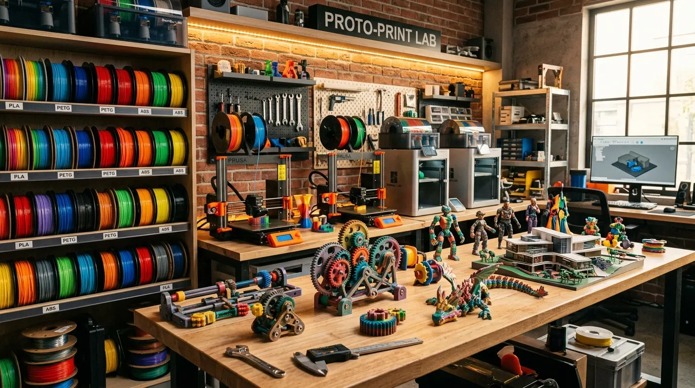
The first 120 seconds, when a 0.2 mm brass nozzle lays down its initial track of thermoplastic across a heated PEI plate at 60 degrees Celsius, dictate the entire fate of a 3D print. A sub-millimeter gap either forms an unbreakable mechanical bond or reduces hours of automated fabrication into a tangled nest of discarded plastic fibers.
In the early 2010s, when open-source RepRap tinkerers wrestled with soldering irons, unshielded stepper drivers, and manually adjusted thumb-screws, 3D printing was an artisanal endurance test. Today, accelerometer-driven resonance compensation (input shaping), inductive bed-mapping sensors that probe in milliseconds, and 500 mm/s CoreXY kinematics have welcomed additive manufacturing straight into living rooms and engineering offices.
Yet automated convenience has never erased the underlying physics and polymer science. On the contrary: thermal differentials between open and enclosed chambers, the severe filament waste of single-nozzle multi-color systems, the moisture absorption of technical polymers, and slicer toolpath parameters still determine whether an extruded object becomes an end-use structural component or a fragile decorative shell.
This guide moves beyond casual forum anecdotes to deliver an authoritative engineering breakdown of modern desktop additive manufacturing—spanning kinematic architectures, multi-material toolchangers, 3MF data structures, filament polymer chemistry, and workshop maintenance protocols.
⚡ Desktop Additive Manufacturing at a Glance
| Primary Feedstock | FDM: 1.75 mm thermoplastic spools | SLA: 405 nm UV-curable photopolymer liquid resin [1] |
| Standard Layer Height | FDM: 0.08 mm – 0.28 mm (Baseline: 0.20 mm) | SLA: 25 – 50 microns (0.025 – 0.05 mm) [1] |
| Multi-Material Systems | Single-Nozzle Purge (AMS/CFS) or Multi-Toolchanger / IDEX [2][3] |
| Thermal Chamber Needs | PLA/PETG/TPU: Open frame | ABS/ASA/PA/PC: Passively heated insulated enclosure (45–60°C) |
| Post-Processing Cycle | FDM: Mechanical support removal & deburring | SLA: IPA solvent wash & UV curing [1] |
| File Container Format | Modern 3MF (Geometry, color mapping & profile archive) vs legacy STL [4] |
1. Fabrication Architectures: FDM vs. Vat Photopolymerization
Every desktop manufacturing workflow begins with a fundamental fork in raw material state and solidification physics: solid thermoplastic filaments (FDM/FFF) or liquid photopolymer resins (SLA/MSLA).
                    Desktop Additive Architectures
                                  │
         ┌────────────────────────┴────────────────────────┐
         ▼                                                 ▼
FDM / FFF (Molten Filament Extrusion)              SLA / MSLA (Vat Photopolymerization)
  │                                                 │
  ├─► Open Frame (PLA, PETG, TPU)                   ├─► 25-50 Micron Surface Resolution
  └─► Enclosed Chamber (ABS, ASA, PA, PC)           ├─► IPA Wash & UV Curing Demands
                                                    └─► Chemical Toxicity & VOC Management
SLA / MSLA (Resin) Technology: The Operational Cost of Micron Precision
By exposing a tank of liquid photopolymer to targeted UV radiation (typically through a 405 nm monochrome LCD panel), SLA and MSLA machines solidify geometries with exceptional isotropic fidelity. Down to 25 microns (0.025 mm), the layer banding inherent to filament extrusion disappears completely. For tabletop figurines, dental stone replicas, and jewelry investment casting patterns, resin remains the industry baseline [1].
However, optical precision introduces rigid handling hurdles:
- Liquid resins are toxic chemical irritants; nitrile gloves, safety goggles, and dedicated vapor-ventilation are non-negotiable.
- Post-processing requires agitated baths in isopropyl alcohol (IPA), complete surface drying, and controlled secondary UV curing to reach final yield strength.
- Standard decorative resins are intrinsically brittle, exhibiting low impact resistance. Formulations engineered for functional toughness carry premium price tags.
FDM / FFF Technology: The Workhorse of the Prototyping Lab
By feeding solid polymer filament through drive gears into a heated meltzone and depositing it through a microscopic orifice, Fused Deposition Modeling provides unbeatable geometric versatility, structural ductility, and economical raw material costs. Here, machine chassis architecture dictates material boundaries:
- Open-Frame Printers: The build volume remains unshielded from ambient room currents. As extruded plastic cools rapidly, polymers with minimal thermal contraction coefficients—such as Polylactic Acid (PLA), PETG, and flexible TPU—print reliably. They are quiet, cost-effective, and provide unobstructed visual monitoring.
- Enclosed-Chamber Printers: The build volume is sealed within an insulated shell. Radiant heat from the build plate and nozzle builds up internal chamber temperatures between 45°C and 60°C. For engineering polymers with high shrinkage coefficients—such as Acrylonitrile Butadiene Styrene (ABS), ASA, and Polyamides (Nylon)—this ambient heat bath prevents corner lifting (warping) and inter-layer separation (delamination). Enclosed designs also integrate HEPA and activated-carbon filters to capture styrene emissions and volatile organic compounds (VOCs).
2. The First Plot Twist: Multi-Color Extrusion — Single Nozzle (AMS) vs. Toolchanger
Automatic material management systems (Bambu Lab AMS, Creality CFS, Anycubic ACE) normalized printing 4 to 16 colors in a single build. Yet this convenience introduced an acute operational bottleneck: runaway filament waste and extended production times.
Multi-Color FDM Architecture Comparison:

[Single-Nozzle + Material Selector (AMS)]:
Spool A ──┐
Spool B ──┼──► [Mechanical Cutter] ──► [Single Nozzle] ──► [Purge Tower] (100-300% Waste)
Spool C ──┤
Spool D ──┘

[Multi-Toolchanger (Snapmaker U1 / Prusa XL / Bambu H3C)]:
Head 1 (Nozzle 1) ──┐
Head 2 (Nozzle 2) ──┼──► [Direct Toolhead Swap (~5s)] ──► Clean Plate Extrusion (Zero Waste)
Head 3 (Nozzle 3) ──┤
Head 4 (Nozzle 4) ──┘
The Single-Nozzle Purge Dilemma
When multiple filaments share a single heating block, switching materials requires retracting the loaded strand, cutting it flush, advancing the alternate spool, and purging residual pigmented plastic into an auxiliary purge chute (“poop”) and onto a prime tower.
When executed across hundreds of vertical slices, the arithmetic becomes staggering:
- Waste Mass: A decorative figurine weighing 100 grams can easily generate 150 to 250 grams of purge scrap [2].
- Time Multiplier: Each toolpath retraction and purge cycle consumes 40 to 60 seconds. A four-hour single-material job can stretch into a 28-hour multi-color run.
- Thermal Incompatibilities: Transitioning between vastly different thermal grades—such as 200°C PLA and 245°C TPU—through a single nozzle risks chronic clogs and thermal degradation.
The Toolchanger and IDEX Solution
To eliminate this systemic inefficiency, modern kinematic platforms (such as the Snapmaker U1, Prusa XL, and Bambu Lab H3C) incorporate toolchanger architectures with 4 to 9 independent toolheads stationed along dedicated docking docks [3].
- Each toolhead maintains its own dedicated extruder motor, thermistor, and pre-heated nozzle.
- When switching materials, the CoreXY carriage parks the current head and latches onto the subsequent tool in approximately 5 to 7 seconds.
- Near-Zero Waste: Because each nozzle stays dedicated to its own polymer, filament purge requirements drop to almost zero.
- Hybrid Material Synergy: Structural components can be modeled in rigid PLA while complex overhang interfaces receive water-soluble PVA or clean-release PETG support barriers; flexible TPU gaskets can even be deposited directly onto rigid chassis housings.
3. The Digital Pipeline: From Parametric Geometry to Sliced G-Code (STL vs. 3MF)
Before physical deposition occurs, three-dimensional geometry must be translated into Cartesian coordinates and volumetric flow commands (G-code). The underlying data structure plays a vital role in preserving engineering tolerances.
The 1987 Legacy of STL vs. The 3MF Standard
For more than three decades, the additive manufacturing community relied on STL (Stereolithography), developed by 3D Systems in 1987. STL suffers from glaring architectural constraints:
- Raw Triangle Meshes: It approximates curved solids exclusively with planar triangles, introducing polygon faceting on spherical contours.
- Dimensionless Values: STL files store raw numerical coordinates without unit flags (whether millimeter, meter, or inch), frequently triggering scaling errors upon import.
- Zero Metadata: It cannot convey color assignments, material identities, layer profiles, or structural orientations.
The 3MF (3D Manufacturing Format) consortium—led by Microsoft, Autodesk, Ultimaker, and Prusa—engineered a modern replacement [4]:
- A structured XML database packed inside a standardized ZIP compression container.
- It stores the true mathematical boundary representation alongside slicing profiles, nozzle configurations, multi-material boundary maps, and support modifiers.
- It verifies manifold topology natively, guaranteeing that digital geometry forms a watertight, solid volume before slicing.
Slicing Parameters and Structural Mechanics
In modern slicers such as OrcaSlicer, Bambu Studio, and PrusaSlicer, mechanical yield strength is governed by deliberate toolpath settings:
- Perimeters (Wall Loops): The vertical shell boundaries bear tensile and bending loads far more efficiently than internal lattice infill. Increasing wall loops from two to four typically enhances flexural strength by upwards of 70%.
- Infill Pattern and Density: Solid 100% infill is rarely necessary and can introduce severe internal cooling stresses. For functional brackets, 20% to 25% density using isotropic patterns like Gyroid or Cubic delivers uniform multi-axial load distribution.
- Layer Height: For standard 0.4 mm nozzles, 0.2 mm serves as the optimal mechanical baseline. While lower layer heights enhance vertical resolution, they double print duration without proportional tensile gains.
4. Polymer Science: 6 Primary Filament Families and Decision Matrix
Flawless slicing settings and rigid kinematics cannot compensate for an inappropriate raw material. Desktop thermoplastics exhibit radically diverse thermodynamic, mechanical, and environmental behaviors.
Desktop Thermoplastic Spectrum (Thermal & Structural Endurance):

Low Temperature / Accessible ◄────────────────────────► High Temperature / Technical
       [PLA]              [PETG]           [TPU]          [ABS/ASA]          [PA / Nylon]
    T_g: ~55°C         T_g: ~80°C       Shore: 95A       T_g: ~105°C          T_g: ~60-70°C
   (Aesthetic)        (Functional)      (Elastomer)      (Automotive)       (Wear/Gears)
1. Polylactic Acid (PLA): The Aesthetic and Prototyping Baseline
Synthesized from fermented plant starches, bio-based PLA features near-zero thermal shrinkage and superior layer bonding. It represents the easiest material to print, excelling in architectural models, visual prototypes, and decorative enclosures. However, its low glass transition temperature ($T_g \approx 55\text{–}60^\circ\text{C}$) means parts warp quickly inside hot vehicles or in contact with warm liquids. Tough PLA, Silk, Matte, and Wood composites offer versatile cosmetic variations.
2. Polyethylene Terephthalate Glycol (PETG): Balanced Toughness
Modifying standard PET with glycol prevents crystallization, balancing the ease of PLA with the structural resilience of engineering polymers. With a $T_g$ near 80°C and excellent ductility, PETG flexes under shock loading rather than shattering. It prints comfortably in open frames and resists moisture, making it an ideal choice for outdoor sensor brackets and protective casings.
3. Thermoplastic Polyurethane (TPU): Elasticity and Impact Absorption
A true elastomer capable of repeated deformation without permanent yield. Graded along the Shore durometer scale (commonly 95A, 90A, or 85A), TPU forms rugged vibration dampers, bespoke gaskets, intake hoses, and impact bumpers. Its elastic compliance demands direct-drive extruders and conservative speeds (20–30 mm/s) to prevent filament buckling along the drive path.
4. Acrylonitrile Butadiene Styrene (ABS): Industrial Heritage
The standard of consumer appliance housings and LEGO bricks, ABS provides high impact toughness and thermal resistance up to 105°C. However, its high thermal shrinkage coefficient (1–2%) requires a heated enclosure (50°C+) and a 100°C bed to prevent corner curling. Styrene outgassing mandates dedicated activated-carbon air filtration.
5. Acrylonitrile Styrene Acrylate (ASA): The Outdoor Armor
Engineered by substituting ABS’s butadiene rubber with acrylic ester, ASA preserves all the mechanical strengths of ABS while adding comprehensive ultraviolet (UV) radiation immunity. It will not yellow, chalk, or embrittle under decades of direct sunlight, making it the premier choice for automotive exterior parts, drone frames, and marine housings.
6. Polyamide / Nylon (PA): The Wear and Dynamic Fatigue Specialist
Offered primarily as PA6, PA11, and PA12, Polyamide is renowned for low coefficients of friction, superior elongation, and cyclic fatigue resistance. It is the industrial material for gears, sliding bushings, and living hinges. However, its polar molecular structure absorbs atmospheric moisture aggressively; thorough drying at 75–85°C prior to extrusion is mandatory. Specialized tribo-filaments (such as igus iglidur) optimize these friction characteristics for dry-running gear assemblies [5].
| Polymer | Glass Transition ($T_g$) | Tensile Behavior | UV & Weather Resistance | Chassis Needs | Nozzle Material | Moisture Sensitivity |
|---|---|---|---|---|---|---|
| PLA | ~55°C | Moderate – High (Brittle) | Low (Deforms/Fades) | Open Frame | Standard Brass | Low – Moderate |
| PETG | ~80°C | High (Ductile) | Good | Open Frame | Standard Brass | Moderate (Stringing) |
| TPU (95A) | N/A (Elastomer) | High Tensile Recovery | Excellent | Open / Enclosed | Standard Brass | High (Foaming) |
| ABS | ~105°C | High (Ductile) | Poor (UV degradation) | Enclosed Heated | Standard Brass | Moderate – High |
| ASA | ~105°C | High (Ductile) | Outstanding (UV immune) | Enclosed Heated | Standard Brass | Moderate – High |
| PA (Nylon) | ~65–75°C | Extreme (High Toughness) | Moderate – Good | Enclosed Heated | Hardened Steel | Critical (Highly hygroscopic) |
| PA-CF / PETG-CF | Base-dependent | Extreme Flexural Modulus | Matte / Technical | Enclosed / Open | Hardened Steel Mandatory | High |
Blending milled carbon fibers into thermoplastics (PLA-CF, PETG-CF, PA-CF) significantly elevates stiffness (flexural modulus) and conceals visible layer lines beneath a premium matte finish. However, carbon fibers do not boost impact resistance; shortening polymer chains often makes the final component more brittle under shock.
Crucially, suspended carbon fibers act as microscopic grinding needles within the meltzone. A single 1 kg spool of carbon-filled filament can expand a standard 0.4 mm brass orifice to 0.6 mm in hours. Extruding composite filaments requires hardened steel, tungsten carbide, or ruby-tipped nozzles.
5. The Second Plot Twist: The Invisible Enemy — Polymer Hygroscopy and the Oven Trap
A frequent troubleshooting dilemma involves a filament spool that produced clean geometries upon unboxing, but weeks later yields rough surfaces, heavy stringing, and weak inter-layer adhesion. Operators blame stepper motor steps or extrusion flow; the real culprit is molecular: atmospheric hygroscopy.
Moisture Flash-Boiling Inside the 220°C Meltzone:

Solid Polymer + Water Molecules (H2O) ──► Meltzone Heatblock (220°C+)
                                                │
                                                ▼
           [Water Flashes to Steam (100°C -> 1600x Volumetric Expansion)]
                                                │
                                                ▼
     [Micro-Steam Explosions ("Popping Audio") + Cavitation in Extrusion]
                                                │
                                                ▼
            Outcome: Stringing, Surface Voids, Severed Layer Bonds
Polyamides, TPU, PETG, and even PLA draw moisture molecules out of ambient air. When water trapped within the filament hits a 220°C to 260°C nozzle, it instantly flash-boils into steam, expanding in volume by approximately 1,600 times. These microscopic steam eruptions trigger audible popping sounds, induce meltzone cavitation, interrupt laminar polymer flow, and leave hollow voids across structural layers—cutting tensile strength in half.
The Domestic Oven Trap
Internet guides routinely suggest placing saturated spools inside kitchen ovens. However, standard domestic heating elements rely on coarse bimetallic or basic electronic thermostats with hysteresis swings of $\pm 15\text{–}20^\circ\text{C}$. A setting of 50°C can spike to 70°C when the element engages. This overshoot blows past PLA’s glass transition threshold ($55^\circ\text{C}$), fusing adjacent filament coils into an unrecoverable plastic brick.
Engineered Drying Protocols
- Active Filament Dryer Boxes: Employ sealed enclosures equipped with positive-temperature-coefficient (PTC) heating fans and continuous vapor exhausts.
- The Temperature Rule: Maintain drying air temperatures 10°C to 15°C below the polymer’s glass transition temperature ($T_g$):
- PLA: 40°C – 45°C (4–6 hours)
- PETG: 60°C – 65°C (6–8 hours)
- TPU: 50°C – 55°C (6–8 hours)
- ABS / ASA: 70°C – 80°C (4–6 hours)
- PA (Nylon): 75°C – 85°C (8–12 hours)
- Storage Discipline: Once dehydrated, store spools in airtight vacuum bags or gasket-sealed polypropylene containers loaded with active desiccant beads.
6. Workshop Discipline: First-Layer Adhesion Chemistry and Mechanical Maintenance
The most sophisticated toolpaths and highest-grade polymers cannot salvage a build if the foundation shears off the build plate.
The Chemistry of Bed Adhesion: Detergent vs. Alcohol
Textured PEI (Polyetherimide) spring-steel sheets represent the modern industry baseline. However, every time an operator touches the build surface, natural human skin oils (sebum) deposit across the micro-textured pores. This organic lipid film acts as a release barrier, destroying polymer adhesion.
- Isopropyl Alcohol (IPA 99%): Excellent for daily dust wipes. However, when faced with heavy sebum oils, IPA often dissolves the lipids without lifting them, redepositing a thin, uniform greasy film across the plate.
- The True Solution (Dish Soap & Warm Water): Every two to three major prints or whenever adhesion degrades, remove the sheet and wash it with warm water and unperfumed dish soap using a clean sponge. Surfactant molecules encapsulate the lipid chains, rinsing them down the drain. Always air dry or use lint-free towels without touching the active surface.
The 250–300 Hour Maintenance Cycle
Desktop 3D printers are high-cycle electromechanical machines. Neglecting routine service manifests as vertical fine artifacts (VFA), dimensional skew, and layer shift:
- Linear Rails and Guide Rods: Wipe carbon fiber rods clean with dry microfiber cloths (never apply lubricant); clean steel linear rails with solvent, then apply a fine film of synthetic machine oil or lithium grease.
- CoreXY Belt Tensioning: Uneven tension between X and Y belts distorts circular toolpaths into ovals. Verify frequency equalization through the firmware’s integrated input shaping resonance diagnostics.
- Extruder Gear Debris: Continuous retraction cycles grind filament shavings into the dual-drive gear teeth. Clear these residues with a brass wire brush or compressed air to preserve positive filament grip.
7. Conclusion: From Craft to Precision Fabrication
Desktop additive manufacturing has matured beyond a novelty gadget into an accessible micro-factory where software toolpaths intersect with polymer mechanics. Whether producing end-use robotics assemblies or functional tooling jigs, manufacturing success relies on an unbroken chain of disciplined variables: dehydrated feedstock, mathematically sound 3MF boundary geometry, stress-oriented perimeter counts, a degreased PEI build plate, and an enclosure tuned to polymer thermodynamics.
Perhaps the enduring allure of desktop 3D printing lies in this exact transformation: converting a cloud of digital coordinates into an immediate, physical artifact resting in the palm of your hand.
- When analyzing multi-material builds, at what point does the material cost and print duration of single-nozzle purge waste justify upgrading to a dedicated multi-toolchanger architecture?
- When designing a functional mechanical component, is your immediate instinct to increase lattice infill percentage, or do you strategically optimize outer wall loops and principal stress orientations?
References and Technical Sources
- Gibson, I., Rosen, D., & Stucker, B. (2021). Additive Manufacturing Technologies: 3D Printing, Rapid Prototyping, and Direct Digital Manufacturing. Springer. (Photopolymerization and resin curing fundamentals).
- Bambu Lab Support Repository (2024). Multi-Color Printing: Flush Volumes, Waste Minimization and Prime Tower Optimization Guidelines.
- Snapmaker Technical Whitepaper (2025). SnapSwap Toolchanger Architecture and Zero-Waste Multi-Material FDM Systems.
- 3MF Consortium Specification (2024). Core Specification & Materials and Properties Extension for 3D Manufacturing Format. https://3mf.io/specification/
- igus GmbH Technical Documentation (2024). Tribo-Filaments in Additive Manufacturing: Wear Resistance and Friction Coefficients of Polymer Gears.
- ASTM F2792-12a (Standard Terminology for Additive Manufacturing Technologies). American Society for Testing and Materials.


